 Silicon From Scratch
Logic Gates & the 1-bit ALU
Before a processor can add, compare, or decide anything, it has to make choices one bit at a time. Those choices are made by logic gates — the smallest building blocks in all of digital hardware. We'll meet the handful you need, then wire two of them together into your very first ALU.
1's and 0's
Quite a few people know that their phone, laptop, or even microwave run on a bunch of 1's and 0's, but what are these 1's and 0's exactly? Well… it depends!
The 0's are easy — they are 0 Volts (V) or ground in a circuit. The 1's however could be a couple different values depending on the power supply used in the circuit. Often called VDD or VCC, the power supply sets what voltage is read as a '1'. In some applications this '1' or 'high' voltage can be 5V, 3.3V or even 1.8V as technology advances.
We care about these 1's and 0's because they drive the fundamental building blocks of our digital circuits — gates. Gates are driven by wires, each of which carrying a 1 or 0 (most of the time). Depending on the combination of 1's and 0's the gate will send a new signal through the circuit.

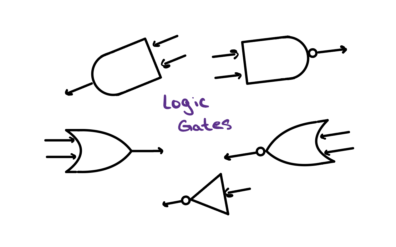
Meet the Gates and their Verilog
There are only a few gates you need to know. Click on each card to flip them and see the Verilog that makes them work!
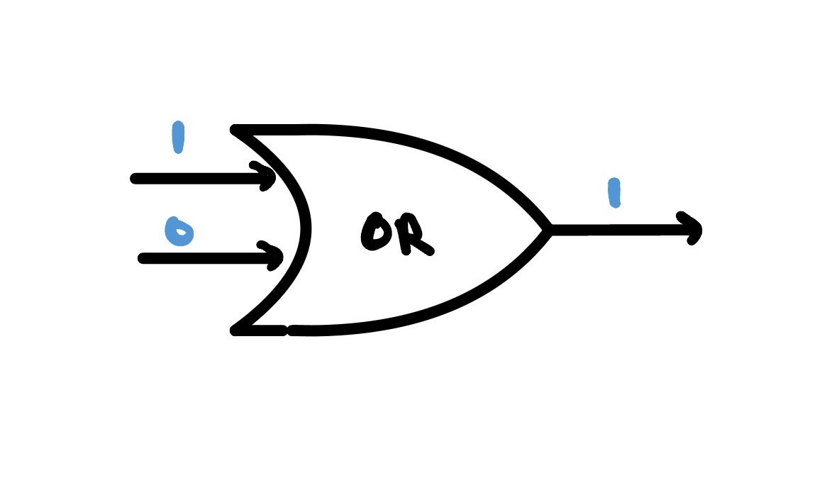
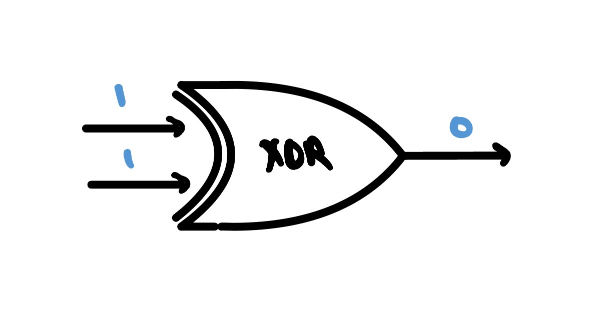
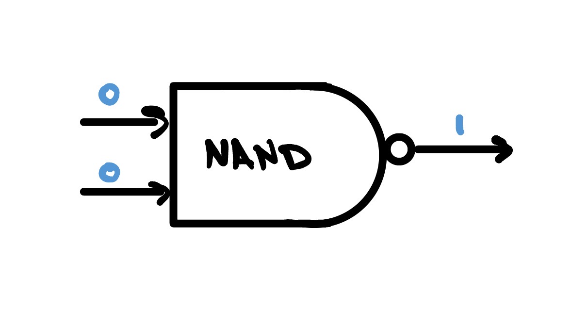
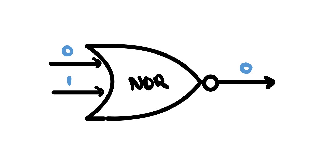
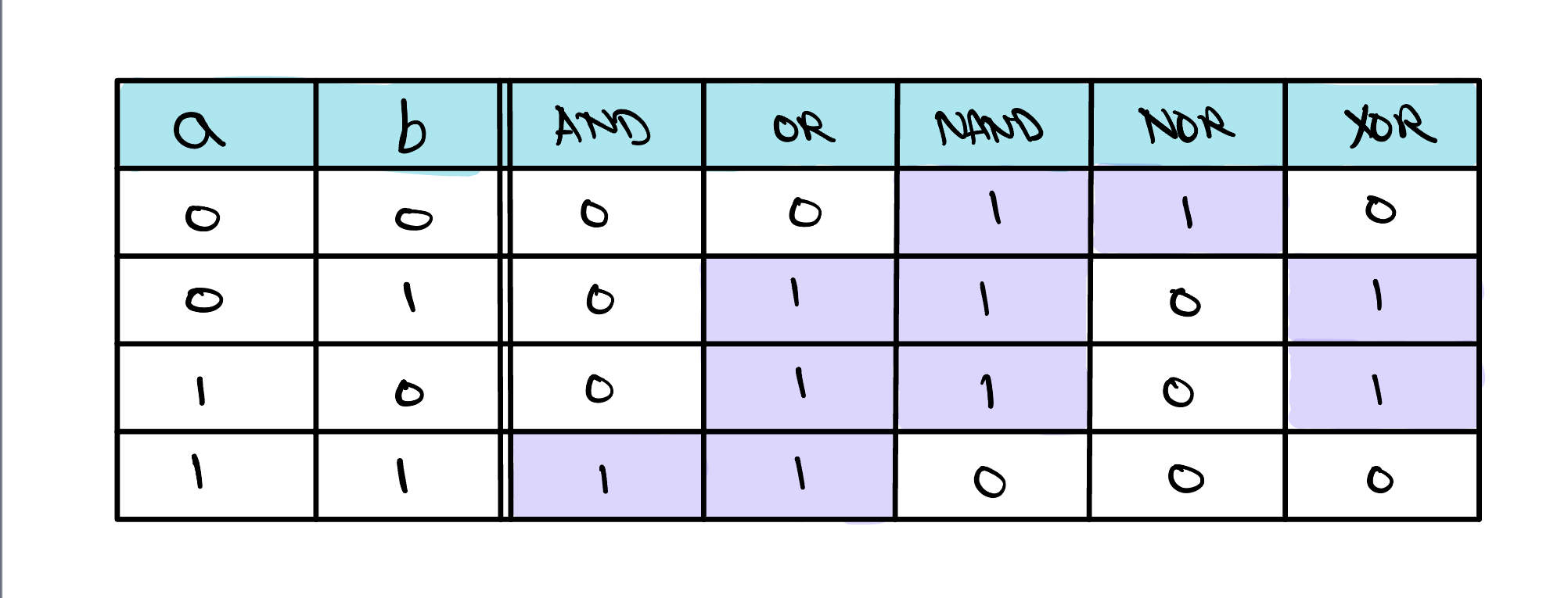
The Truth Table
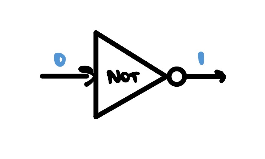
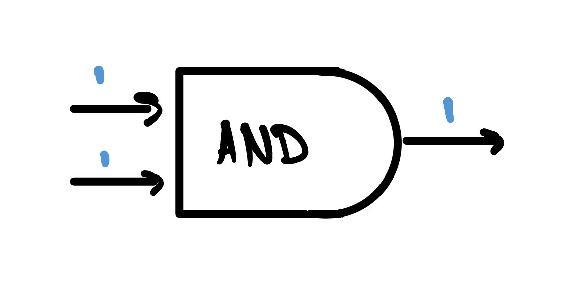
Since each gate only has a few input combinations, we can enumerate all of them with their corresponding outputs in a table. This table is called a truth table, and is an easy way to describe each gate's behavior.
The If-Else of Digital Design
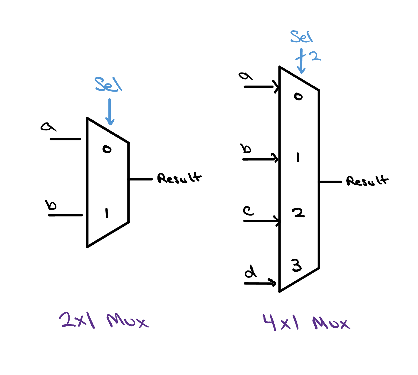
sel signal.
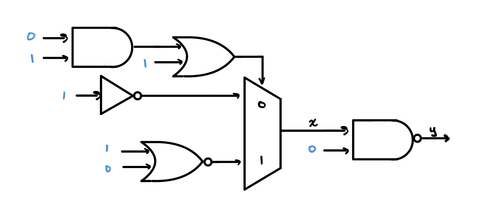
Gates compute answers — but a processor also needs to choose between answers. That job belongs to a multiplexer, or mux: a switch that takes several inputs and a small control signal, and passes exactly one of those inputs through to its output.
A two-way mux is the simplest kind. It has two data inputs, labeled 0 and 1, and a single control wire. When the control is 0 it forwards the first input; when it's 1 it forwards the second. Nothing is computed here! The mux simply decides which existing signal gets to be the output. That single idea is what turns a pile of gates into something that can perform different operations on command.
Muxes come in bigger sizes, too. A 4×1 mux chooses among four inputs, and hence uses a 2-bit control signal to encode all four possibilities. In general, a 2n×1 mux requires an n-bit control signal. The wider the mux, the more operations our ALU will eventually be able to offer.
Your First ALU
Here it is — your first ALU. It may be tiny, but it still packs a
punch! This ALU can perform both AND and OR operations depending on
the value of the operation signal.
That's the whole trick, and it's worth pausing on: with a single
control wire, the same hardware performs two different
operations. The gates do the work; the mux, steered by
operation, chooses which work counts. Scale that idea up
and you have the defining feature of an ALU — one block that carries
out whichever operation the processor asks for.
Here's how we'll build on this:
- More operations. Widen the multiplexer, hang more circuits off of it, and above all addition, which needs a new building block called a full adder.
- More bits. Real processors work on 32 or 64 bits, not one. We'll line up copies of this slice side by side and pass a carry between them so they can add large numbers together.
- Status flags. A full ALU also reports about its result, which is what allows us to perform comparisons between inputs. ALUs also have overflow detection built in, so the processor can figure out how to deal with super large or super small results.
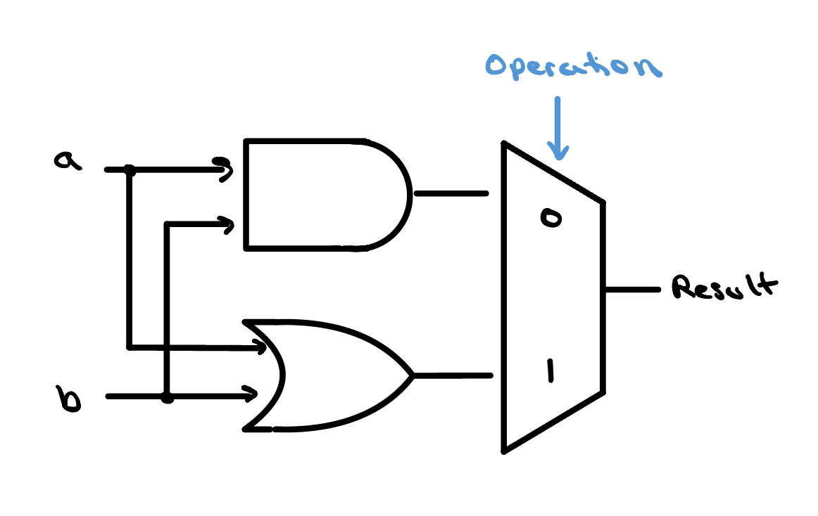
operation bit picks the result. We'll make it cooler,
don't worry.